Since the mounting shaft of the stud and the stud head have the eccentricity of between 0.4 mm to 1.0 mm, the position of this Eccentric Cam Follower can easily be fine adjusted by turning the stud, achieving a compact, highly accurate integrated structure.
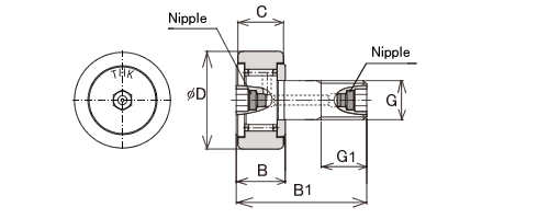
A hexagon socket is provided on both ends of the stud, and a grease nipple is placed inside the stud from the each end.


Dimensional drawing  
Model No. Main dimensions Basic load rating Detail specifications CAD Dimensional drawing
Outer 
diameter
D
Threaded
G
Outer ring 
width
C

B
Overall
length
B1
With cage Full-roller type 2D 
(DXF)
3D
Dynamic rating
C
Static rating
C0
Dynamic rating
C
Static rating
C0
mm mm mm mm mm kN kN kN kN
CFH 12-AB 30 M12×1.5 14 15 40 7.87 9.79 13.4 19.8
CFH 12-1-AB 32 M12×1.5 14 15 40 7.87 9.79 13.4 19.8
CFH 16-AB 35 M16×1.5 18 19.5 52 12 18.3 20.6 37.6
CFH 18-AB 40 M18×1.5 20 21.5 58 14.7 25.2 25.2 51.3
CFH 20-AB 52 M20×1.5 24 25.5 66 20.7 34.8 33.2 64.8
CFH 20-1-AB 47 M20×1.5 24 25.5 66 20.7 34.8 33.2 64.8
CFH 24-AB 62 M24×1.5 29 30.5 80 30.6 53.2 46.7 92.9
CFH 24-1-AB 72 M24×1.5 29 30.5 80 30.6 53.2 46.7 92.9
CFH 30-AB 80 M30×1.5 35 37 100 45.4 87.6 67.6 145
CFH 30-1-AB 85 M30×1.5 35 37 100 45.4 87.6 67.6 145
CFH 30-2-AB 90 M30×1.5 35 37 100 45.4 87.6 67.6 145